Classifieds rule 5 - adverts must have the username and date in photos. Adverts failing rule 5 will be deleted

Sewdhull
Members-
Posts
591 -
Joined
-
Last visited
-
Feedback
0%
Content Type
Profiles
Forums
Buy a Patch
Classifieds
Everything posted by Sewdhull
-
I've only got one detent on my WE. I was able to stop reward travel of the selector plate with an extended case screw, but I'm presuming it goes too far forward in your case.
-
Make sure both sides of the selector lever are even. If the right side is misaligned it will keep the safety on. Only the last bit of travel removes safety. That spring looks meaty too. Also I suggest putting a ball bearing in the lh selector instead of plastic it you have a plastic detent in place. You can use one off an old thrust bearing. Selector plate issue I'm unsure what you mean
-
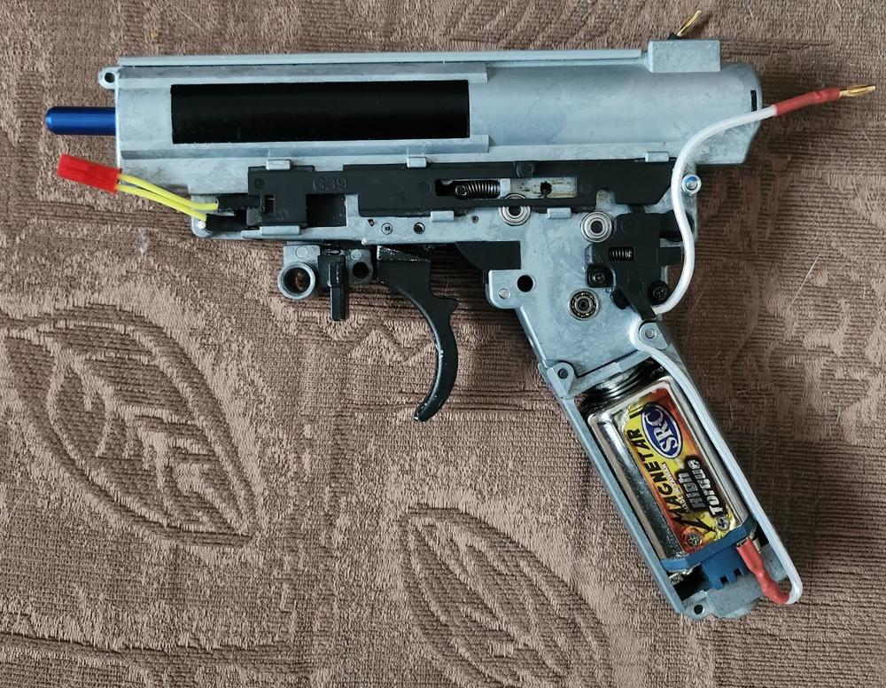
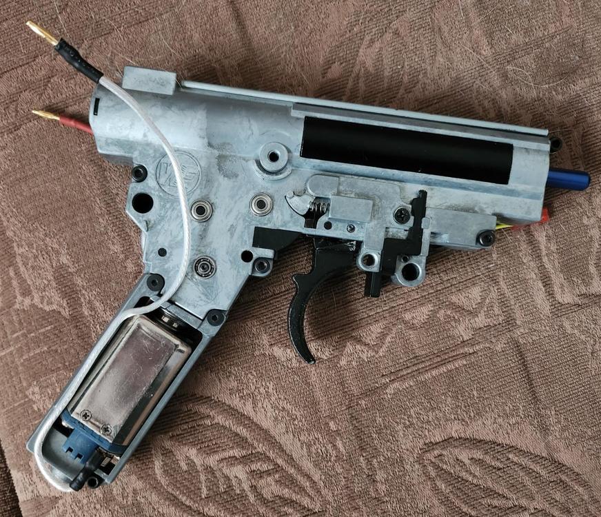
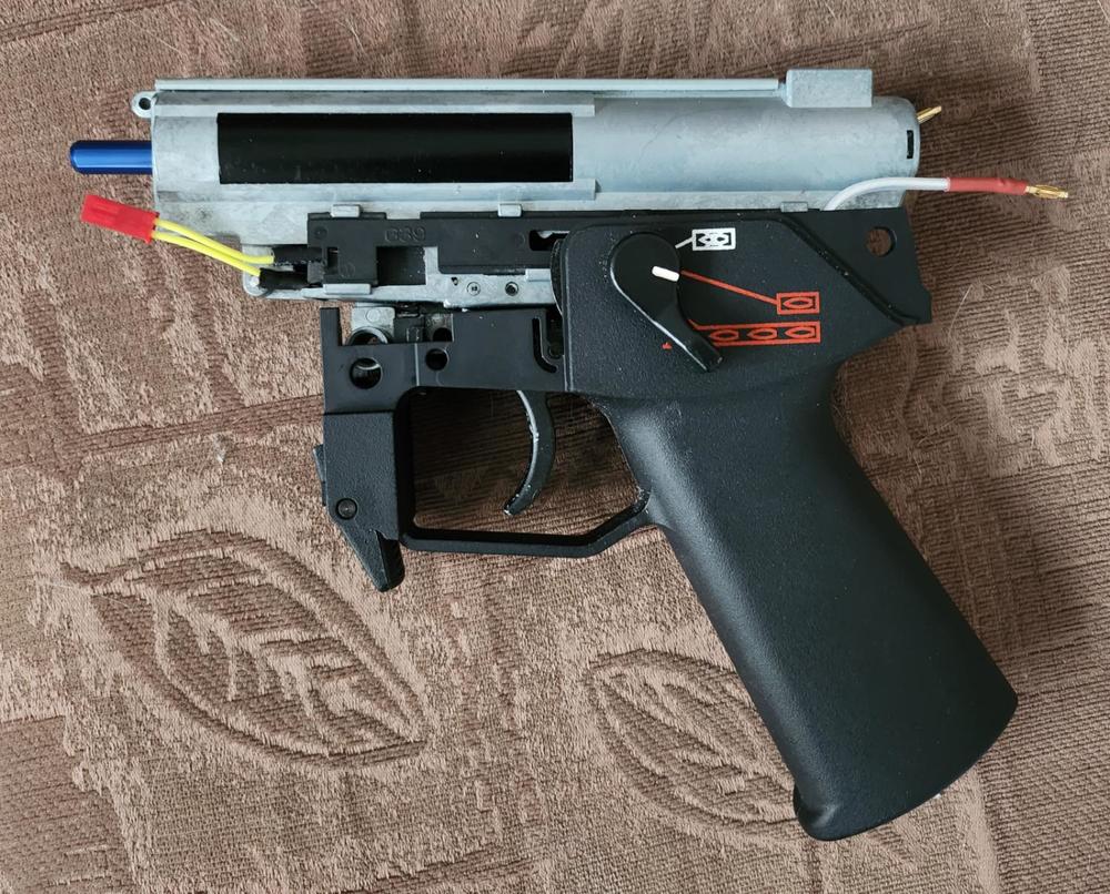
Hello, I fancied a DMR so I thought I would convert my G36k I think it is. There's nothing special going in, just a stronger spring and a simple MOSFET for the trigger. Here's the gearbox, I'll add more as I get on with it. I was able to lock it to semi by using a longer gearbox bolt and adding a nut to the end of it to restrict the selector plate travel. I can use teflon wire with this since I don't need or want the flexibility of silicone. It's thinner too for the same gauge. There's a working bolt cover latch on the model and a reversal latch release on the selection of safety( the black bit just above the motor on pic 1) The battery will be in the front with the MOSFET. Bolt cover catch ahead of the trigger in the above pic. Connectors for the MOSFET trigger in yellow wire and the motor with the bullet connectors at the rear, which will go forward through the body of the gun.
-
Me too, not a zener. I've looked at the lists again, there's some voltage regs in 5 pin. More than one sadly. https://smd.yooneed.one/code5931.html That's your y1s and whilst they are mostly zeners, there's a few regulator, detecting, etc ics in 5 pin. I've looked at a few of them and we need to know the connections. If you know which pins get volts etc you can look at the pin outs from the data sheets in alldata or some such. It's likely a generic variety since there's so little info on the package. Do you have that bit of the circuit written out?
-
It's a zener diode mate. 25 to 2.5v Likely 9v or 16v depending on what it's doing.
-
Uh magnets seem overkill for a 150w motor, but the specs look all but the same. https://m.airsoftmotor.com/airsoft-motor/long-shaft-aeg-motor/high-speed-39k-cnc-brushless-airsoft-motor.html
-
My understanding of precocking is that it's just a delay in removing power after the trigger is released. This won't affect the motor or MOSFET. AB is more problematic, if it's shorting the motor it's possible to damage the motor electronics and no reason to suspect AB even works on a brushless.
-
It looks like it's a guide for the nozzle to centre it as it gets close to the hop rubber. The nozzle in these goes quite deep into the hop and may be pushed up by the bbs on the underside and the plastic bit at the top pushes it down towards the centre of the opening which is quite snug. Maybe the BB too. There may be some consistency advantage having the bbs pushed in by the nozzle in this manner.
-
Its the paint scratching isnt it? I guess you can leave the plastic barrel in place but the wear on it may be more, soft plastic vs hard metal sort of thing. Functionally it shouldn't make any difference. I thought a tilting outer barrel was necessary to allow the slide to reciprocate even if the inner barrel was fixed, like the M and P for example. I've had a look and the no tilting barrels are made so they don't fit into the slide recess but sit below it, so it doesn't need to tilt to clear the slide, awesome, another learning day.
-
Again back in the day we added spacers to precompress the springs...
-
In my co2 mags for a we big bird there is a fine mesh which serves to reduce pressure. You may be able to fill the mesh to reduce the area that lets gas through. However it's the rocket or flute valve in the bbu that determines how much gas goes down the barrel. Reducing the spring tension or putting a spacer in to reduce its travel will serve to close the valve quicker. It seems the knocker, which presses the valve on the mag stays in place until the slide reciprocates and it's the flute valve that when it's pushed shut allows the pressure to operate the slide. https://youtu.be/IeQWC3-5YTo?si=0Dv3r9OlPbaiLQUG
-
I can measure my mag release (cyma mp5) if you want, you measure yours and compare? The TM one has two grub screws the others have one. The TM one is an anodized machined aluminium part ( maybe cast or from a lump) and the others, mim.
-
I don't know how handy you are but if you epoxy the two parts together, drill it out and sleeve it with brass tube. Or print one https://cults3d.com/en/3d-model/gadget/cm041-sd-silencer-mounting
-
https://www.patrolbase.co.uk/cyma-cm-041-sd-aeg-silencer-mounting-apparatus It's out of stock here.
-
Currents, 7.4 and 11.1 22tpa xt 17 and 25 BL xt. 15.5 and 20.5. Ah I forgot to take precocking off...wondered why auto was so similar to semi if not a little more. The BL is much faster, esp at 7.4v in comparison, but I haven't sorted my feeding issue. BL motor isn't fitted properly I can tell, I'll have to have look see when I've a bit more time.
-
You need some sort of electronic commutation and sensors plus a lil computer to work out when to commutate. The main difficulty in making the BL motor like a brushed motor is that the BL needs power to work, MOSFETs have a polarity and the board needs electrical protection that Brushed ones don't. There's a circuit on the board to supply power to the electronics and the tab voltage will go via the MOSFETs to the windings switched at the right time to make the motor spin the right way using the sensors on the endbell. Made the right way you can power the device with PWM, switch the MOSFETs on and let the windings see the PWM signal. It is likely however that fault conditions will be detected if the averaged voltage drops in the PSU. MOSFETs must have enough voltage, from the PSU via the controller not the tabs, to fully turn on or they get hot and magic smoke escapes so this condition is avoided. The PSU should be polarity protected but the MOSFETs can't be because of the diodes protecting the MOSFET from the motor. I noticed the perun load the motor to detect it making it try to turn. If other ETUs don't do this correctly for BL motors that's not the motors fault. ETUs need to bear in mind brushless motors exist. BL motors can brake themselves with a change in timing and probably do, which will always make AB a problem on them. If the AB MOSFET on the ETU shorts the motor it will stop doing things and no braking will occur when the MOSFETs are off. If the motor is shorted in pulses, to lessen the effect of the braking then the MOSFET may remain on if the PSU still has power and there may be braking. If braking is effected by reversing the polarity then this is bad news and magic smoke may escape. BL motors may detect shorts to prevent damage and stop working with any AB. If AB is to be effected on a BL motor the motor should do it, and could with the right programming and circuit. I notice the board has a 78L05 regulator on it and some other PSU bit around the +tab. That reg has a minimum input voltage of 7v (there will be wiggle room) to regulate 5v out.
-
The motor has to follow the same form factor as existing motors and a single case for long and short motors makes sense, at least for the smaller producers. I don't think there's a case for a reversable motor, unless you can think of a reason why you'd want such a thing. Brushless motors can't be very dumb, they need the controller, the large flat chip, to do the sums to make it turn etc. You need additional wiring terminals to do anything via the ETU because 1, the ETU expects to deliver only voltage to the motor terminals, and 2, the motor expects to see voltage only to the motor terminals. You may find the motor controller already brakes the motor to control the back EMF at motor stop. Given the right message the motor can spin any way you want it to but you'd need some sort of interface to achieve it and the controller programming and it needs power.
-
As a motor, the brushless is 1mm shorter, compared to the xt brushed, from the motor front to the pinion end, the motor tower has no play in it. Altho I would suggest this dimension could be adjusted as the shaft was probably a bit longer originally. The motor appears to have strong magnets, and the stepping between them very apparent when you rotate the motor. Motor tabs are strong. I notice the tabs are nearer the motor ends, which caused me no issues but may in different grips at the end. There is room to bend the tabs through 90degrees which is an option you don't see usually. Don't bend the tabs lol. I'm really happy with this motor so thank you xt. This weekend I'll run this and the xt brushed through the ammeter and see what that reveals.
-
I fitted mine to test and it functions just as the brushed motor does. I have a perun. Motor height was different and it needed to be screwed in further. It fit without issue I think perhaps I'll look at bevel height as I've got motor tower play which I removed on the brushed motor. Or shim the tower to fit the hole in the gearbox casing. I haven't fired any bbs through it yet but it fires normally on 7.4 and 11.1 lipo, a 7.4 lion and a 9.9 life.
-
Yeah diameters of stuff varies from model to model I found.
-
I think muffs disappeared in the 90s
-
In the video there is mention of speed tests to come. The actual speed of the motor will be load dependant, but a decent brushless will see higher loaded speeds because of the reduced losses and increased torque usually seen. The brushless motors that allow ab etc need a capacitor to maintain the voltage to the control electronics on the motor. I'm unsure if AK has had a peek to see if such a capacitor exists.
-
I'll sort out the feed issues running both, but start with 7.4v, then 9.9v then 11v. However the gears are 13:1 and the motor might run too fast with 11s. I wanted a low motor speed, the 22tpa might be too fast on those gears, which I can vary with the perun but I'd rather not have to so I can run with a brushless. At the moment the bbs don't drop into the hop and rely on the mag spring pushing them into the chamber, which is either hop rubber in the way or nozzle, or a combination of the 2. I'm not after RPS so 7.4v would be fine but I think the brushless likes 11.1 so we shall see. I don't think the brushless would like motor speed reduction via the perun.
-
Mines going in the Mp5 once I sort out the feed issue


